


| Quantity: | |
|---|---|


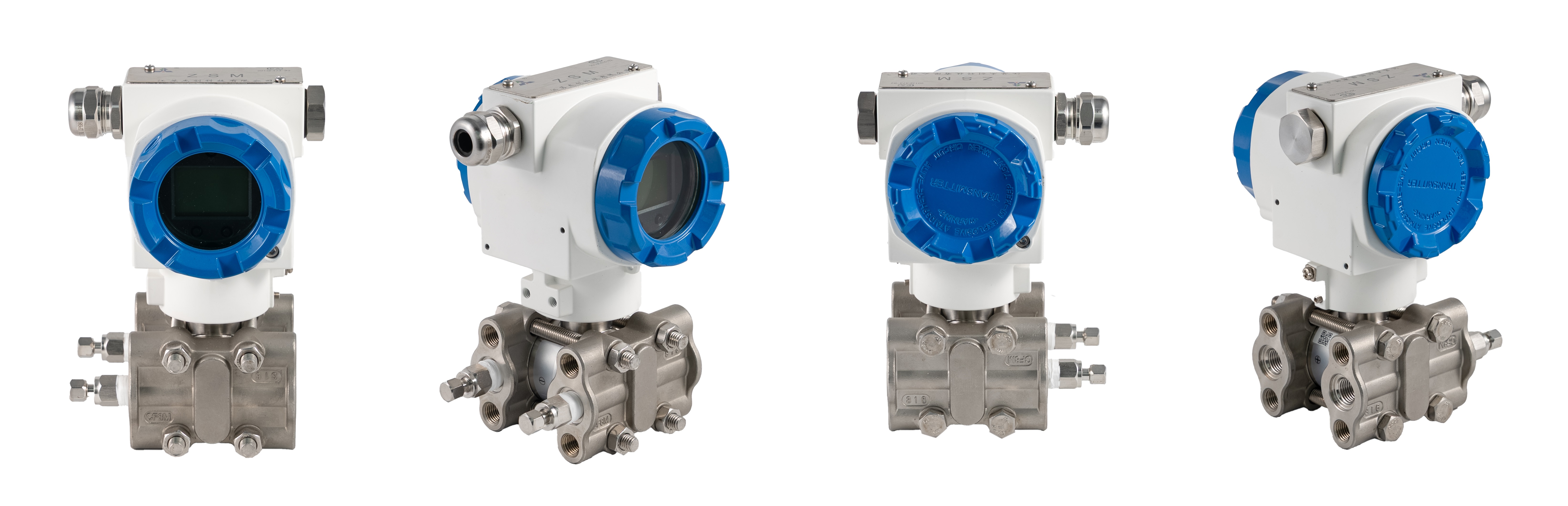
JC-G-DR/DP
JIECHUANG
Intelligent Differential Pressure Transmitter 4-20mA + Hart Digital Display
Product Overview
A Differential Pressure (Flow) Transmitter is a crucial instrument used in various industrial processes to measure the difference in pressure between two points within a system. This differential pressure is directly proportional to the flow rate of the medium, making the transmitter an essential component in flow measurement and control applications.
These transmitters are designed with high precision and reliability to ensure accurate measurement of differential pressure, even in harsh environments. The device typically consists of a sensor, transmitter, and display unit, all integrated into a compact and robust housing. It can measure the pressure difference across flow elements such as orifice plates, Venturi tubes, and other flow restrictions, converting this data into an electrical signal that can be easily monitored and recorded.
Product Features
● High Accuracy:
The differential pressure (flow) transmitter achieves high accuracy measurements within the range of -4 to 40 kPa, with a standard calibration accuracy of ±0.075%. It provides exceptional overpressure performance even at low ranges.
The 40 kPa standard range chip can withstand a reverse overpressure of up to 8 MPa.
● Excellent Environmental Adaptability:
Equipped with intelligent static pressure and temperature compensation, the transmitter is protected from the effects of temperature, static pressure, and overpressure, minimizing the overall measurement error on-site.
Flexible range compression capabilities:
S1, S2 range ratio: 4:1
M1 to M4 range ratio: 50:1
L1 range ratio: 100:1
● Superior Operability and Convenience:
Comes with a 5-digit backlit LED display with multiple display units (mA, Pa, kPa, MPa, bar, mbar, %, psi, mmH2O).
Built-in three-button quick operation for on-site adjustments.
Available in various corrosion-resistant materials.
Comprehensive self-diagnostic functions.
● High Stability:
Available ranges: 1 kPa, 6 kPa, 40 kPa, 100 kPa, 400 kPa, 4 MPa, 40 MPa.
Exceptional overpressure performance.
Standard HART communication.
Self-diagnostic function.
Product Specifications
● Measured Fluid: Liquid, gas, steam
● Measurement Range:
Range | kPa | mbar | mmH2o |
S1 | -1 ~ 1 | -10~ 10 | -100 ~ 100 |
S2 | -6 ~ 6 | -60 ~ 60 | -600 ~ 600 |
M1 | -40 ~ 40 | -400 ~ 400 | -4000 ~4000 |
M2 | -100 ~ 100 | -1000 ~ 1000 | -10000~10000 |
M3 | -200 ~ 200 | -2000 ~ 2000 | -20000 ~ 20000 |
M4 | -400 ~400 | -4000 ~ 4000 | -40000 ~ 40000 |
L1 | -4000 ~ 4000 | -40000 ~ 40000 | -400000 ~ 400000 |
● Operating Pressure:
Diaphragm Box | Range (kPa) | Unilateral Overpressure(Mpa) | Bilateral Static Pressure (MPa) |
S1 | -1 ~1 | 1 | 1 |
S2 | -6 ~ 6 | 2 | 2 |
M1 | -40~ 40 | 3 | 3 |
M2 | -100 ~ 100 | 8 | 8 |
M3 | -200~ 200 | 8 | 8 |
M4 | -400 ~ 400 | 8 | 8 |
L1 | -4000 ~ 4000 | 10 | 10 |
● Output Signal: 4 ~ 20mA DC + HART Protocol
● Allowable Load Resistance: 0 ~ 600Ω (at 24V DC)
Note: When communicating with a handheld communicator, a standard load resistance of 250Ω is required.
● Power Supply: General Purpose: 10.5 ~ 45V DC; Intrinsically Safe: 10.5 ~ 26V DC
● Communication Line Conditions:
Line Length: Maximum 2km (use 0.75 ~ 1.25mm² control cable; for distances over 1km, use twisted pair cable)
Load Resistance: 250 ~ 600Ω (at 24V DC, including cable resistance)
Load Capacitance: Below 0.55mF
Load Inductance: Below 3.3mH; ensure power lines are separated by at least 15cm (avoid parallel wiring)
● Saturation Current: Upper Limit 20.8mA, Lower Limit 3.8mA
● Alarm Current: Upper Limit 22.8mA, Lower Limit 3.6mA (mode configurable)
● Adjustment Function: Zero and full-scale adjustment can be done locally via three buttons on the transmitter or remotely using configuration software.
● Output Modes: Linear Output, Square Root Output (remotely adjustable via configuration software)
● Operating Temperature: -40 ~ +85℃ (When filled with fluorine oil: -10 ~ +60℃)
● Storage Temperature: -40 ~ +100℃
● Weather Resistance: DIN40040GPC
● EMS Applicable Standard: EN1326-1:2006
Performance Specifications
● Accuracy:
Diaphragm Box | Reference Accuracy |
S1, S2, M1, M2, M3, M4, L1 | TD1:1…TD15:1 = ±0.075% |
TD > 15:1 =±(0.0015×TD+0.075)% |
● Square Root Output Accuracy:
Output | Accuracy |
≥50% | Same as reference accuracy |
50% to falling point | Same as reference accuracy × 50 Square root output (%) |
● Environmental Temperature Impact:
Total impact quantity at 28℃ (50°F) | |
Diaphragm Box | Impact |
M1, M2, M3 | ±[0.08% of the range + 0.015% of the upper range limit] |
M4, L1 | ±[0.08% of the range + 0.03% of the upper range limit] |
● Static Pressure Impact: ±0.05% of the range for 10MPa
● Process Impact: ±0.05% of the range limit for 10MPa
● Stability: ±0.05% of the range limit per year
● Power Supply Impact: ±0.005% per 1V
● Installation Position Impact: Installing parallel to the diaphragm surface won't cause zero drift. If the installation position deviates more than 90° from the diaphragm surface, zero drift within a range of 0.4kPa can be corrected by zero calibration.
● Response Time: 90ms
● Damping: Time constant can be adjusted within the range of 0 to 99.9 seconds.
● Filter Constant: Can be adjusted within the range of 0 to 160uA.
● Self-stabilization Coefficient: Can be adjusted within the range of 0 to 2%.

"Power Supply Voltage vs. External Load Relationship Diagram"
Material Structure
● Liquid sealing ring: Fluororubber, nitrile rubber (optional)
● Transmitter casing: Low copper aluminum die-casting + polyurethane coating
● Transmitter casing cover: Low copper aluminum die-casting + polyurethane coating
● Protection level: IP66
● Nameplate: SUS304
● Filling oil: Silicone oil, fluorine oil (optional)
● Dimensions: According to the outline drawing
● Weight: Approximately 2.9 ~ 3.1 kg (main body)
● Cable entry port: M20×1.5
● External terminal: M4 screw
● Process connection port: 1/4-18NPT
● Installation method: Install with U-bolts on a 50mm (2-inch) pipeline
Electrical Connection Diagram

Product Dimensional Diagram


